This time i introduced the concept of Virtual Port-Channel, also known as VPC, in my lab since it’s a very used feature in real datacenter scenario. With VPC you can attach a downstream device (switch, router, server, firewall, …) in “dual-homing” mode to 2 different Nexus switch, the VPC peers or members. In your downstream device you simply need to configure a classic port-channel (lacp) while on Nexus side you need to create a VPC domain in order to synchronize the data-plane maintaining a separate control-plane. Synchronization task will be made through the peer-link while the vpc domain state is guaranteed by the keep-alive link.
Lab topology is:
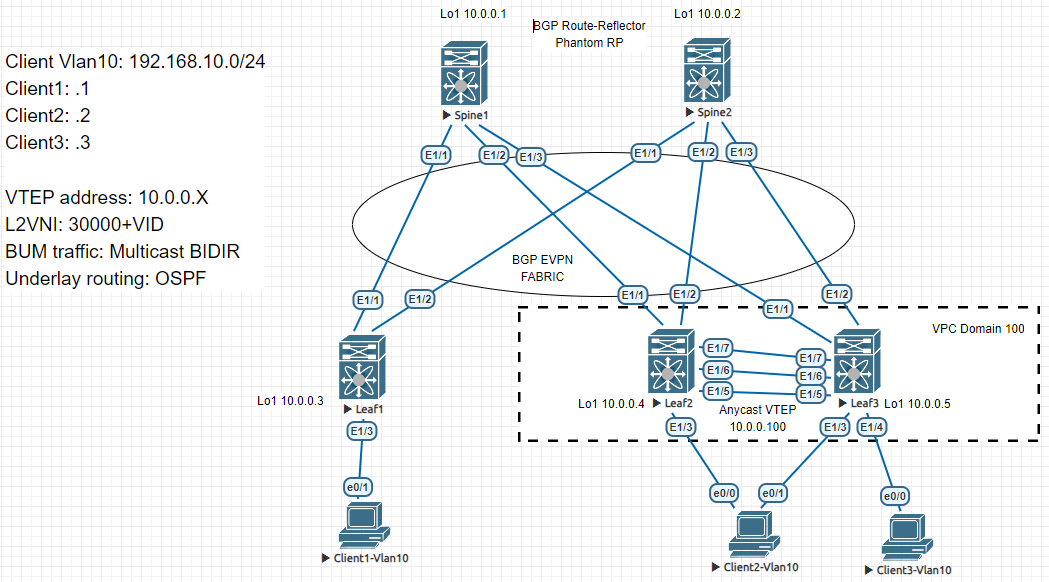
VPC configuration consist in:
- configure a routed port or a SVI for the keepalive link
- configure a port-channel for the VPC peer-link (trunk mode where all the vlans are allowed)
- configure VPC domain
- configure a downstream port-channel with the VPC tag
e.g. Leaf2

feature vpc

interface Ethernet1/7
  description VPC KEEPALIVE
  no switchport
  vrf member KA
  ip address 169.254.0.1/30
  no shutdown

interface Ethernet1/5
  switchport mode trunk
  channel-group 5 mode active

interface Ethernet1/6
  switchport mode trunk
  channel-group 5 mode active

interface port-channel5
  description VPC PEER-LINK
  switchport mode trunk
  spanning-tree port type network
  vpc peer-link

vpc domain 100
  peer-switch
  peer-keepalive destination 169.254.0.2 source 169.254.0.1 vrf KA
  ip arp synchronize

interface Ethernet1/3
  switchport access vlan 10
  channel-group 3 mode active

interface port-channel3
  description Client2-Vlan10
  switchport access vlan 10
  vpc 3
After the proper configuration you can see the VPC status and verify all the consistency check are good
e.g. Leaf2

Leaf2# show vpc
Legend:
                (*) - local vPC is down, forwarding via vPC peer-link

vPC domain id                     : 100
Peer status                       : peer adjacency formed ok
vPC keep-alive status             : peer is alive
Configuration consistency status  : success
Per-vlan consistency status       : success
Type-2 consistency status         : success
vPC role                          : primary
Number of vPCs configured         : 1
Peer Gateway                      : Disabled
Dual-active excluded VLANs        : -
Graceful Consistency Check        : Enabled
Auto-recovery status              : Disabled
Delay-restore status              : Timer is off.(timeout = 30s)
Delay-restore SVI status          : Timer is off.(timeout = 10s)
Operational Layer3 Peer-router    : Disabled
Virtual-peerlink mode             : Disabled

vPC Peer-link status
---------------------------------------------------------------------
id    Port   Status Active vlans
--    ----   ------ -------------------------------------------------
1     Po5    up     1,10

vPC status
----------------------------------------------------------------------------
Id    Port          Status Consistency Reason                Active vlans
--    ------------  ------ ----------- ------                ---------------
3     Po3           up     success     success               10
VPC introduced a related concept in our VXLAN fabric lab, the Anycast VTEP. Since we have a device attached to 2 different VTEPs, each one with its own VTEP address (Lo1), each VTEP advertise RT2 or R5 information to all the others VTEPs with its own VTEP address. In order to avoid this kind of situation we can add a secondary ip address (the same for both the VPC peers!) to our VTEP interface. In this mode the VPC peers automatically advertised RT2 or RT5 informations sourced with the Anycast VTEP address:
e.g. Leaf2

interface loopback1
  description VTEP addresses
  ip address 10.0.0.4/32
  ip address 10.0.0.100/32 secondary
  ip router ospf UNDERLAY area 0.0.0.0
  ip pim sparse-mode
As we can see, Client2 (aabb.cc80.7000) and Client3(aabb.cc00.1000) are advertised with the Anycast VTEP address:
Leaf2# show bgp l2vpn evpn vni-id 30010
BGP routing table information for VRF default, address family L2VPN EVPN
BGP table version is 67, Local Router ID is 10.0.0.4
Status: s-suppressed, x-deleted, S-stale, d-dampened, h-history, *-valid, >-best
Path type: i-internal, e-external, c-confed, l-local, a-aggregate, r-redist, I-injected
Origin codes: i - IGP, e - EGP, ? - incomplete, | - multipath, & - backup, 2 - best2

   Network            Next Hop            Metric     LocPrf     Weight Path
Route Distinguisher: 10.0.0.4:32777    (L2VNI 30010)
*>l[2]:[0]:[0]:[48]:[aabb.cc00.1000]:[0]:[0.0.0.0]/216
                      10.0.0.100                        100      32768 i
*>i[2]:[0]:[0]:[48]:[aabb.cc00.6010]:[0]:[0.0.0.0]/216
                      10.0.0.3                          100          0 i
*>l[2]:[0]:[0]:[48]:[aabb.cc80.7000]:[0]:[0.0.0.0]/216
                      10.0.0.100                        100      32768 i
In the lab i also decide to change the BUM traffic management system from ingress-replication to multicast bidir. Multicast bidir is the best way to go with VXLAN because it create only 1 shared-tree for the 2-way traffic (request and reply) instead of 2 different trees (1 for request traffic and 1 for reply) created by AnySource Multicast (sparse mode). The bidir configuration is quite simple, you only need to create a Loopback interface with an address that belong to the same subnet of the phantom RP and then declare the phantom RP on every nodes:
e.g. Spine1

interface loopback101
  ip address 10.0.0.253/30
  ip router ospf UNDERLAY area 0.0.0.0
  ip pim sparse-mode


e.g. Spine2

interface loopback101
  ip address 10.0.0.253/29
  ip router ospf UNDERLAY area 0.0.0.0
  ip pim sparse-mode


e.g. Each nodes

ip pim rp-address 10.0.0.254 bidir
With the bidir configuration, no multicast source-tree exist anymore (S,G) but only a shared-tree (*,G) for that particular multicast group:
Leaf1# sh ip mroute 239.0.0.10
IP Multicast Routing Table for VRF "default"

(*, 239.0.0.10/32), bidir, uptime: 00:18:49, nve pim ip
  Incoming interface: Null, RPF nbr: 0.0.0.0
  Outgoing interface list: (count: 1)
    nve1, uptime: 00:18:49, nve


Leaf1# sh ip pim rp
PIM RP Status Information for VRF "default"
BSR disabled
Auto-RP disabled
BSR RP Candidate policy: None
BSR RP policy: None
Auto-RP Announce policy: None
Auto-RP Discovery policy: None

RP: 10.0.0.254, (1),
 uptime: 00:57:35   priority: 255,
 RP-source: (local),
 group ranges:
 224.0.0.0/4  (bidir)
This is not sufficient in order to achieve our reachability goal, we also need to adjust the nve interface configuration:
interface nve1
  no shutdown
  host-reachability protocol bgp
  source-interface loopback1
  member vni 30010 mcast-group 239.0.0.10
At this point all the pieces are in the right place, we have the correct information in the BGP table, in the l2route table and finally in the mac address table:
Leaf1# sh bgp l2vpn evpn
BGP routing table information for VRF default, address family L2VPN EVPN
BGP table version is 158, Local Router ID is 10.0.0.3
Status: s-suppressed, x-deleted, S-stale, d-dampened, h-history, *-valid, >-best
Path type: i-internal, e-external, c-confed, l-local, a-aggregate, r-redist, I-injected
Origin codes: i - IGP, e - EGP, ? - incomplete, | - multipath, & - backup, 2 - best2

   Network            Next Hop            Metric     LocPrf     Weight Path
Route Distinguisher: 10.0.0.3:32777    (L2VNI 30010)
*>i[2]:[0]:[0]:[48]:[aabb.cc00.1000]:[0]:[0.0.0.0]/216
                      10.0.0.100                        100          0 i
* i                   10.0.0.100                        100          0 i
*>l[2]:[0]:[0]:[48]:[aabb.cc00.6010]:[0]:[0.0.0.0]/216
                      10.0.0.3                          100      32768 i
*>i[2]:[0]:[0]:[48]:[aabb.cc80.7000]:[0]:[0.0.0.0]/216
                      10.0.0.100                        100          0 i
* i                   10.0.0.100                        100          0 i

Route Distinguisher: 10.0.0.4:32777
* i[2]:[0]:[0]:[48]:[aabb.cc00.1000]:[0]:[0.0.0.0]/216
                      10.0.0.100                        100          0 i
*>i                   10.0.0.100                        100          0 i
* i[2]:[0]:[0]:[48]:[aabb.cc80.7000]:[0]:[0.0.0.0]/216
                      10.0.0.100                        100          0 i
*>i                   10.0.0.100                        100          0 i

Route Distinguisher: 10.0.0.5:32777
* i[2]:[0]:[0]:[48]:[aabb.cc00.1000]:[0]:[0.0.0.0]/216
                      10.0.0.100                        100          0 i
*>i                   10.0.0.100                        100          0 i
* i[2]:[0]:[0]:[48]:[aabb.cc80.7000]:[0]:[0.0.0.0]/216
                      10.0.0.100                        100          0 i
*>i                   10.0.0.100                        100          0 i


Leaf1# show l2route mac topology 10

Flags -(Rmac):Router MAC (Stt):Static (L):Local (R):Remote (V):vPC link
(Dup):Duplicate (Spl):Split (Rcv):Recv (AD):Auto-Delete (D):Del Pending
(S):Stale (C):Clear, (Ps):Peer Sync (O):Re-Originated (Nho):NH-Override
(Pf):Permanently-Frozen, (Orp): Orphan

Topology    Mac Address    Prod   Flags         Seq No     Next-Hops
----------- -------------- ------ ------------- ---------- ---------------------------------------
10          aabb.cc00.1000 BGP    Rcv           0          10.0.0.100 (Label: 30010)
10          aabb.cc00.6010 Local  L,            0          Eth1/3
10          aabb.cc80.7000 BGP    Rcv           0          10.0.0.100 (Label: 30010)


Leaf1# sh mac address-table
Legend:
        * - primary entry, G - Gateway MAC, (R) - Routed MAC, O - Overlay MAC
        age - seconds since last seen,+ - primary entry using vPC Peer-Link,
        (T) - True, (F) - False, C - ControlPlane MAC, ~ - vsan
   VLAN     MAC Address      Type      age     Secure NTFY Ports
---------+-----------------+--------+---------+------+----+------------------
C   10     aabb.cc00.1000   dynamic  0         F      F    nve1(10.0.0.100)
*   10     aabb.cc00.6010   dynamic  0         F      F    Eth1/3
C   10     aabb.cc80.7000   dynamic  0         F      F    nve1(10.0.0.100)
And reachability happens:
Client1-Vlan10#sh ip arp
Protocol  Address          Age (min)  Hardware Addr   Type   Interface
Internet  192.168.10.1            -   aabb.cc00.6010  ARPA   Ethernet0/1
Internet  192.168.10.2           84   aabb.cc80.7000  ARPA   Ethernet0/1
Internet  192.168.10.3           78   aabb.cc00.1000  ARPA   Ethernet0/1

Client1-Vlan10#ping 192.168.10.2
Type escape sequence to abort.
Sending 5, 100-byte ICMP Echos to 192.168.10.2, timeout is 2 seconds:
!!!!!
Success rate is 100 percent (5/5), round-trip min/avg/max = 9/12/17 ms

Client1-Vlan10#ping 192.168.10.3
Type escape sequence to abort.
Sending 5, 100-byte ICMP Echos to 192.168.10.3, timeout is 2 seconds:
!!!!!
Success rate is 100 percent (5/5), round-trip min/avg/max = 10/12/15 ms
In the next VXLAN lab i will introduce the concept of Anycast gateway and routing between different L2VNI.